
Carbon Paper vs Carbon Cloth GDL for PEM Fuel Cells
Carbon Paper vs Carbon Cloth GDL: How to Choose for a PEM Fuel Cell MEA
Carbon paper and carbon cloth can both serve as the porous backing of a gas diffusion layer in a PEM fuel cell. They perform the same broad jobs—moving reactant gases toward the catalyst layer, conducting electrons and heat, helping remove product water, and supporting the membrane electrode assembly—but their fiber architectures create different mechanical and processing behavior. The correct choice depends on the complete GDL construction and the cell hardware, not on the substrate name alone.
In practical purchasing, carbon paper is usually selected when a thin, flat, dimensionally stable backing is important. Woven carbon cloth is often considered when flexibility, toughness during handling, or conformity to the assembly is useful. These are tendencies rather than guarantees. Grade, thickness, PTFE treatment, microporous layer, compression, surface roughness, permeability, electrical resistance, flow field, and gasket stack-up can outweigh the paper-versus-cloth label.
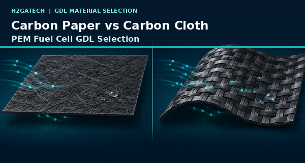
Conceptual comparison of nonwoven carbon paper and woven carbon cloth substrate architectures.
The Short Answer
Choose carbon paper when the design benefits from a relatively flat, thin, precisely cut substrate with predictable in-plane dimensions. Consider carbon cloth when a woven, flexible, mechanically robust backing is preferred for handling or conformity. Then validate the finished GDL—not just the bare backing—because PTFE treatment and the catalyst-facing microporous layer can change water behavior, gas transport, contact, thickness, and surface condition.
Carbon Paper vs Carbon Cloth GDL at a Glance
Review point | Carbon paper | Carbon cloth | Buyer interpretation |
Fiber architecture | Nonwoven or pressed carbon-fiber structure | Woven bundles of continuous carbon fibers | Architecture affects surface, anisotropy, compression, and handling. |
Handling | Flat and easy to register, but some grades can be brittle | Flexible and resistant to bending damage; cut edges may fray | Evaluate automated and manual handling with the actual cut geometry. |
Surface and thickness | Often thinner and flatter for a given application class | Often thicker and more textured because of the weave | Use finished, measured values rather than category assumptions. |
Compression response | Can give a firm stack-up but may crack if mishandled | Can conform more readily; weave and thickness can change local compression | Specify pressure-dependent thickness and resistance when critical. |
Cutting and edges | Well suited to precision die or plotter cutting when supported | May require controls for fraying, fiber pullout, and orientation | Inspect manifold holes, sealing edges, and loose fibers. |
Typical selection logic | Thin, flat, repeatable GDL stack-up | Flexible, robust, conformable backing | Neither is universally superior; approve the complete construction in-cell. |
What Is a Carbon Paper GDL Substrate?
Carbon paper is made by forming short or chopped carbon fibers into a porous nonwoven sheet and consolidating them with a carbonized binder system. The resulting network can be thin, flat, and relatively uniform in thickness. In fuel-cell production, those characteristics can simplify registration, cutting, inspection, and gasket stack-up. Carbon paper is widely used as a GDL backing, especially where low thickness and scalable sheet or roll processing matter.
Its main handling caution is brittleness. A grade can crease, crack, shed fibers, or damage an MPL if bent too tightly or gripped at an unsupported edge. “Carbon paper” also covers a broad family: fiber length, binder, porosity, thickness, surface condition, and compression response differ by manufacturer and grade. The name alone is not a finished specification.
What Is a Carbon Cloth GDL Substrate?
Carbon cloth is a woven structure made from continuous carbon-fiber yarns or bundles. Plain, twill, satin, and other weave patterns produce different thickness, drape, surface relief, and directional properties. The woven network is usually more flexible than carbon paper and can tolerate repeated bending and handling more readily.
That flexibility does not eliminate engineering controls. Woven edges may fray, loose filaments can intrude into a sealing area, and the fabric surface can be rougher or more anisotropic. Thickness may also be larger and more pressure-dependent. A cloth grade should therefore be identified by manufacturer, grade, weave or orientation if relevant, treatment, MPL, finished dimensions, and measured compressed properties.
Substrate Format Is Only the First Decision
The bare backing is not always the part that contacts the catalyst layer. Many commercial GDLs add hydrophobic treatment and a microporous layer (MPL). The MPL uses much finer carbon particles and binder to create a smoother catalyst-facing interface, reduce the risk of fiber contact with the membrane, and help balance gas and liquid-water transport. It can make two different backings behave more similarly at the catalyst interface—or make two products with the same backing behave very differently.
A quotation should therefore separate four items: substrate family, exact grade, PTFE or other wet-proofing treatment, and MPL construction. Also state which side faces the catalyst layer. A substrate code does not automatically confirm that treatment or an MPL is included.
For related catalyst-coated diffusion-media options, review H2gatech Gas Diffusion Electrode.
Compression, Sealing, and Stack-Up
A GDL operates under compression between the bipolar-plate lands and the CCM. Too little compression can leave poor electrical and thermal contact or allow gas leakage. Excessive compression can reduce pore volume, increase transport resistance, damage an MPL, deform the substrate into channels, or create local stress at the membrane. Paper and cloth may reach the same nominal thickness through very different compression behavior.
For a useful comparison, report uncompressed thickness and thickness at one or more stated pressures. If area-specific resistance or permeability is important, give the test pressure and fixture method. The gasket should be evaluated with the chosen GDL as one compressed stack-up. Replacing paper with a thicker cloth without revisiting the seal design can change contact pressure and leak margin even when the active area is unchanged.
To define all included layers before quotation, see CCM vs MEA: What Fuel Cell Buyers Should Specify.
Gas Transport and Water Management
The U.S. Department of Energy describes the GDL as the pathway that distributes reactant gases, conducts current, and helps remove product water. Carbon paper and carbon cloth can both perform these functions, but their pore networks are not interchangeable. Fiber arrangement, porosity, tortuosity, PTFE distribution, MPL structure, compression, and channel-to-land pattern determine the working transport path.
Do not infer flooding resistance from flexibility or surface texture. A hydrophobic cloth may still show poor transport if compressed too heavily, while a carefully matched paper/MPL construction may manage water effectively. Conversely, a paper selected only for low thickness may be too restrictive in a wet, high-current-density cathode. Compare candidates under dry and wet operating limits, not only at one nominal polarization condition.
Cutting, Edge Condition, and Orientation
Carbon paper generally supports clean, repeatable outlines and hole patterns when the cutting method and support are appropriate. Carbon cloth may need additional control for fraying, yarn displacement, and loose filaments. In either format, fibers or debris in a manifold or gasket path can create leakage, electrical shorts, or assembly variation.
Orientation can matter. Woven cloth is visibly directional, and nonwoven paper can also show machine-direction properties. If the flow field, cut shape, or mechanical design is sensitive to direction, mark the orientation on the drawing and packaging. Record which face carries the MPL and which face contacts the catalyst layer.
A Practical Matched-Sample Validation Plan
Validation stage | What to control or record |
1 Freeze the comparison | Keep CCM, active area, GDL treatment, MPL target, gasket, plates, clamping method, and operating protocol constant. |
2 Characterize incoming material | Record grade, weave or orientation, dimensions, mass, uncompressed thickness, surface condition, edges, and MPL defects. |
3 Measure under pressure | Compare compressed thickness, resistance, permeability or other critical properties at stated pressures. |
4 Assemble consistently | Use the same tightening sequence, compression target, break-in, gas conditions, temperature, and humidification. |
5 Test the operating window | Include nominal performance plus dry, wet, high-current, pressure-differential, cycling, and start-stop conditions as relevant. |
6 Inspect after testing | Review imprint, deformation, fraying, cracks, MPL damage, fiber intrusion, water pattern, and dimensional change. |
7 Approve the full construction | Freeze substrate grade, treatment, MPL, orientation, finished thickness, inspection, packaging, and change control. |
H2gatech Engineering Note
When a customer requests “carbon cloth GDL” because it is flexible, or “carbon paper GDL” because it is thin, H2gatech should translate that preference into measurable finished-part requirements. The most useful starting information is the cell drawing, active area, anode and cathode use, target thickness, PTFE basis, MPL requirement, flow field, land/channel geometry, gasket stack-up, compression method, humidity range, pressure, current-density window, and acceptance test.
For a new design, use a controlled sample matrix rather than changing several materials at once. First compare candidate backings with closely matched treatment and MPL. Then optimize treatment or MPL on the preferred backing. Finally confirm the complete MEA in the intended hardware with repeat samples. This keeps the reason for a performance change visible and makes later production control more meaningful.
Use this information framework before sample production: How to Specify a Custom Fuel Cell MEA.
For another practical carbon-paper comparison, read SIGRACET 28 BC vs Toray TGP-H-060.
RFQ Checklist for Carbon Paper or Carbon Cloth GDL
RFQ section | Information to provide or agree |
Application | PEM fuel-cell type, active area, anode or cathode, duty cycle, target current density, and project stage |
Substrate | Carbon paper or cloth; manufacturer and grade; weave/orientation if relevant; thickness; acceptable alternatives |
Treatment | PTFE or other treatment, reporting basis, side, target or tolerance, and verification method |
MPL | Required or not, catalyst-facing side, loading/thickness basis, binder constraints, and surface criteria |
Dimensions | Outer profile, active area, manifold holes, datums, orientation marks, tolerances, and edge criteria |
Finished properties | Uncompressed/compressed thickness, mass, resistance, permeability, flatness, and visual defects |
Cell hardware | Flow field, land/channel geometry, gasket material and thickness, plates, and clamping method |
Operating conditions | Temperature, humidity, gases, pressure, differential pressure, stoichiometry, cycling, and storage |
Quality and supply | Sample quantity, lot traceability, inspection report, packaging, change notification, forecast, and approval plan |
Common Selection Mistakes
• Treating carbon paper as rigid and carbon cloth as flexible without checking the actual grade and finished construction.
• Comparing bare paper with an MPL-coated cloth, then attributing every difference to the substrate format.
• Replacing paper with cloth while keeping the original gasket thickness and compression target unchanged.
• Ignoring cloth fraying, fiber orientation, loose filaments, or edge condition around manifold and sealing features.
• Using only uncompressed thickness instead of pressure-dependent thickness and resistance.
• Selecting from a single polarization curve without repeat samples, wet/dry challenges, and post-test inspection.
• Approving a substrate code without freezing treatment, MPL, orientation, finished properties, and change control.
Frequently Asked Questions
Is carbon cloth GDL always more durable than carbon paper?
Carbon cloth is generally more tolerant of bending and handling, but durability in a cell depends on the grade, treatment, MPL, compression, cycling, and interfaces. A cloth can fray or deform, while a suitable paper can perform reliably when handled and compressed correctly.
Is carbon paper always thinner than carbon cloth?
Many fuel-cell carbon papers are thinner than woven cloths, but this is not a universal rule. Compare finished thickness at an agreed pressure, including PTFE treatment and MPL.
Which substrate is better for high current density?
Neither category is automatically better. High-current performance depends on gas transport, water removal, electrical contact, MPL, compression, flow field, and operating conditions. Use matched in-cell testing.
Can carbon cloth replace carbon paper without changing the gasket?
Not safely by assumption. Different thickness and compression behavior can change sealing and contact pressure. Recalculate the compressed stack-up and verify leak and electrical performance.
Does the same GDL have to be used on both sides of the MEA?
No. The anode and cathode may use different substrates, treatments, or MPLs. If they differ, drawings, labels, packaging, and assembly controls must identify each side clearly.
What information is needed for a quotation?
Provide substrate preference or qualified grade, finished dimensions, thickness basis, treatment, MPL, anode/cathode use, cell hardware, compression, operating window, sample quantity, and acceptance plan.
Discuss a Custom GDL or MEA With H2gatech
Send H2gatech your active area, cut drawing, preferred paper or cloth grade, treatment and MPL requirements, anode/cathode use, gasket stack-up, compression method, operating conditions, validation protocol, sample quantity, and documentation needs. The engineering team can help organize a traceable comparison before the GDL construction is frozen. Contact H2gatech to discuss the project.
Technical References
• U.S. Department of Energy — Parts of a Fuel Cell — official overview of GDL gas distribution, current conduction, water removal, PTFE wet proofing, and MPL function.
• SGL Carbon — SIGRACET Gas Diffusion Layers — official description of carbon-paper GDL backing, PTFE treatment, MPL, compression, thickness, and scalable production considerations.
• AvCarb — Carbon Fabric — official examples of woven carbon-fabric structures, weave patterns, thickness ranges, and continuous-roll formats.