
PTFE Treated Carbon Paper Selection Guide
5% vs 20% PTFE-Treated Carbon Paper: How to Specify a PEM Fuel Cell GDL
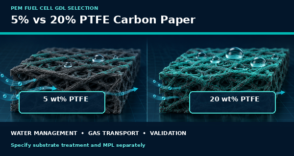
The practical difference between 5% and 20% PTFE-treated carbon paper is not simply that one is “slightly hydrophobic” and the other is “more waterproof.” PTFE changes how the porous carbon backing interacts with liquid water, but it can also change pore accessibility, gas transport, surface contact, mass, thickness, and the way an added microporous layer behaves. A higher percentage is therefore not automatically better.
Before comparing two products, confirm what the percentage means. It may describe the target dry PTFE mass fraction in the treated substrate, the concentration of the treatment bath, or PTFE in a separate microporous layer. These are not interchangeable specifications. The correct GDL should be selected from the complete construction and validated in the intended PEM fuel cell hardware.
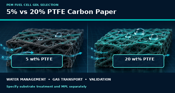
Conceptual comparison: hydrophobicity, pore access, and cell validation must be considered together.
The Short Answer
A 5 wt% treatment is often used as a relatively light wet-proofing level, while 20 wt% represents a substantially larger PTFE addition. The lighter treatment may preserve more open pore volume and gas access; the heavier treatment may provide a stronger liquid-water-repellent effect but can also occupy pore space or increase transport resistance. The actual result depends on PTFE distribution, substrate structure, heat treatment, MPL, compression, humidity, current density, and flow-field design.
Do not choose from the percentage alone. Specify the measurement basis, carbon-paper grade, treated side or full-sheet treatment, MPL presence and PTFE content, finished thickness, compressed properties, orientation, and acceptance test. Compare matched samples under the same cell conditions.
5% vs 20% PTFE Carbon Paper at a Glance
Review point | 5 wt% PTFE | 20 wt% PTFE | Buyer interpretation |
Nominal PTFE level | Lower target addition | Higher target addition | Confirm whether the value is final dry uptake, bath concentration, or another basis. |
Hydrophobic effect | Can improve wet proofing while retaining a relatively open substrate | Can increase water repellency and liquid-entry resistance | Surface distribution can matter as much as bulk percentage. |
Gas transport risk | Usually less polymer occupying the pore network | More potential for pore blockage or added diffusion resistance | Measure the finished part; do not infer permeability from percentage alone. |
Water-management risk | May provide less flooding margin in some wet conditions | May retain too little water or restrict transport in another design | The optimum changes with humidity, current density, pressure, and flow field. |
Finished thickness and mass | Smaller treatment contribution in principle | Larger treatment contribution in principle | Report actual finished values after treatment and heat processing. |
Best purchasing use | Controlled sample option in a defined validation matrix | Controlled sample option in the same matched matrix | Approve the complete GDL construction, not a PTFE number in isolation. |
First Define What the PTFE Percentage Means
The phrase “5% PTFE” can hide several different calculations. One supplier may report the dry mass of PTFE divided by the final treated substrate mass. Another may describe the concentration of the aqueous dispersion used for dipping. A third may report PTFE as a fraction of the carbon-plus-PTFE solids in the MPL. Those numbers can look identical on a quotation while describing different materials.
A 2026 experimental study comparing 5%, 20%, and 50% target treatments showed why the distinction matters: achieved PTFE uptake was measured by mass before and after treatment, and the actual value depended on the substrate and treatment response. For purchasing, the RFQ should state the calculation basis and the method used to verify or control it.
Possible reporting basis | What it describes | Why it must be clarified |
Treatment-bath concentration | PTFE solids concentration in the liquid used for impregnation | Does not directly equal final dry PTFE in the carbon paper. |
Dry substrate uptake | Mass increase attributed to PTFE after drying and heat treatment | Requires an agreed weighing, conditioning, and calculation method. |
Final treated-paper wt% | PTFE mass divided by the final treated substrate mass | Useful only when supplier and buyer use the same denominator. |
MPL PTFE wt% | PTFE fraction within the dry MPL solids | Separate from PTFE already present in the macroporous backing. |
Coating add-on | Mass per area added by treatment or MPL | Report in mg/cm² or g/m² with the included materials identified. |
Separate Substrate Treatment From the Microporous Layer
A PEM fuel cell GDL usually has a macroporous carbon backing, and many finished GDLs add a finer microporous layer on the catalyst-facing side. PTFE can be present in the backing, in the MPL, or in both. The U.S. Department of Energy explains that hydrophobic PTFE helps keep transport pores open while the MPL can adjust the balance between water retention and water release.
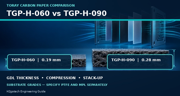
If a quotation says only “Toray TGP-H-060, 20% PTFE,” it still does not establish whether an MPL is included. Toray distinguishes carbon paper from Torayca GDL products that add a microporous coating. The buyer should list the substrate treatment and MPL as separate line items, including which side faces the catalyst layer.
For a related finished-GDL comparison, read SIGRACET 28 BC vs Toray TGP-H-060.
How More PTFE Can Help and Hurt
Increasing PTFE generally makes the carbon surface less wettable and can increase the pressure required for liquid water to enter or pass through the pore network. That can be useful when the cathode faces condensation or flooding. At the same time, added polymer can coat fibers, change pore size and tortuosity, reduce accessible void volume, and alter electrical or thermal contact. A treatment that improves one water-management condition can create a gas-transport penalty elsewhere.
The distribution is not necessarily uniform. PTFE may concentrate near a surface, around native binder, or at specific pore junctions. Heat treatment, dispersion stability, immersion or coating method, drying, and substrate chemistry can all influence the final structure. This is why a contact-angle photo or a nominal wt% does not replace permeability, resistance, thickness, and single-cell testing.
Why 20% Is Not Automatically Better Than 5%
Published fuel-cell studies do not identify one PTFE percentage as a universal optimum. Experimental comparisons of 5 wt% and 20 wt% treatments show that transport and cell performance depend on substrate microstructure, PTFE distribution, pressure, humidity, current density, and the specific test method. These results should guide a sample plan, not become a universal purchasing rule.
The correct engineering question is therefore not “Which percentage is best?” It is “Which complete GDL construction maintains reactant access, removes excess liquid water, avoids membrane dry-out, preserves contact, and remains stable across our operating window?”
Anode and Cathode Requirements May Differ
The cathode produces water and is often the first side considered when discussing flooding. The anode has different gas composition, humidification, water flux, and contaminant exposure. Using the same treated carbon paper on both sides simplifies purchasing and assembly, but it should not be assumed to be optimal. A development plan may keep one side fixed while varying the other to identify the source of a change.
If the two sides use different treatment levels or MPL constructions, drawings, packaging, and inspection records must identify the anode and cathode unambiguously. The MPL normally faces the catalyst layer. Do not rely on surface appearance alone during assembly.
To confirm which layers are supplied together, see 3-Layer MEA vs 5-Layer MEA.
Compression and Finished Thickness Still Matter
PTFE treatment can change mass and may change the finished thickness or compression response. The GDL then operates between the bipolar-plate lands and the catalyst-coated membrane. Too little compression can leave poor electrical contact; excessive compression can reduce porosity, damage an MPL, increase local stress, or promote intrusion into flow channels. The gasket and GDL must be evaluated as one compressed stack-up.
Specify whether thickness is measured before or after treatment, with or without an MPL, and at what conditioning state. For compressed thickness or area-specific resistance, state the applied pressure and fixture method. A nominal 5% or 20% treatment does not replace these finished-part requirements.
A Practical Matched-Sample Validation Plan
Validation stage | What to control or record |
1 Freeze the baseline | Use the same CCM, substrate grade, cut geometry, MPL status, gasket, plates, active area, and assembly procedure. |
2 Define the treatment | Record target and actual PTFE basis, treatment side, processing lot, finished mass, thickness, and orientation. |
3 Inspect incoming samples | Check dimensions, flatness, visible nonuniformity, edge condition, MPL cracks or shedding, and identification. |
4 Confirm cell assembly | Record gasket relationship, compression method, tightening sequence, leak result, and initial contact resistance. |
5 Test the operating window | Use matched break-in, temperature, humidity, pressure, stoichiometry, current-density steps, and repeat samples. |
6 Challenge dry and wet limits | Include the conditions most likely to cause membrane dry-out, condensation, flooding, or oxygen-transport loss. |
7 Review post-test evidence | Inspect imprint, deformation, water pattern, MPL damage, delamination, fiber intrusion, and dimensional change. |
8 Approve the full construction | Freeze substrate, substrate PTFE, MPL composition, finished thickness, inspection, packaging, and change control. |
H2gatech Engineering Note
When a customer requests “Toray 060 with 5% PTFE” or “20% waterproof carbon paper,” H2gatech should first confirm whether the request is for treated backing only, an MPL-coated GDL, or a gas diffusion electrode with catalyst. The next checks are the PTFE reporting basis, finished thickness, MPL side, anode or cathode use, active area, gasket, compression, humidity range, and acceptance method.
For a new PEM fuel cell design, a small matrix is more informative than changing several variables at once. One practical sequence compares 5% and 20% treated backing with the same substrate and no MPL; the next compares matched MPL constructions; the final choice is then confirmed in the intended MEA and cell hardware. This preserves a clear link between material change and test result.
For the complete information needed before sample production, use How to Specify a Custom Fuel Cell MEA.
For catalyst-coated diffusion-media options, review H2gatech Gas Diffusion Electrode.
RFQ Checklist for PTFE-Treated Carbon Paper
RFQ section | Information to provide or agree |
Application | Fuel-cell type, active area, side, duty cycle, current-density range, and project stage |
Carbon backing | Manufacturer and grade, thickness, dimensions, fiber orientation if relevant, and acceptable alternatives |
PTFE treatment | 5%, 20%, or other target; reporting basis; treatment method or class; side; tolerance; verification method |
MPL | Required or not, catalyst-facing side, carbon and binder constraints, loading or thickness basis, surface criteria |
Finished properties | Uncompressed and compressed thickness, mass, permeability, resistance, flatness, and defect criteria |
Cell hardware | Flow-field design, land/channel geometry, gasket material and thickness, plate material, and clamping method |
Operating conditions | Temperature, humidity, pressure, stoichiometry, gases, contaminants, cycling, freeze or storage needs |
Quality and supply | Sample quantity, lot traceability, inspection report, packaging, change notification, forecast, and approval plan |
Common Purchasing Mistakes
• Using “5% PTFE” without defining the denominator or whether the number belongs to the substrate or MPL.
• Assuming the treatment-bath concentration equals the final dry PTFE uptake in every carbon paper.
• Ordering a Toray substrate code and assuming that PTFE treatment and an MPL are automatically included.
• Selecting 20% only because it sounds more water resistant, without checking gas transport and dry-operation behavior.
• Comparing two samples that also differ in substrate thickness, MPL loading, compression, gasket, or test protocol.
• Applying one cathode result to the anode without separate verification.
• Approving a GDL from a single polarization curve without repeat samples, wet/dry challenges, and post-test inspection.
Frequently Asked Questions
Does 20% PTFE always prevent flooding better than 5%?
No. A higher PTFE level can increase water repellency, but distribution, pore blockage, MPL, compression, humidity, current density, and flow field determine the cell result. Test both options under the intended wet operating conditions.
Is 5% PTFE better for gas permeability?
It may preserve a more open pore network, but the finished permeability depends on the substrate, treatment distribution, MPL, processing, and compression. Request measured finished-part data when permeability is critical.
Does TGP-H-060 include 5% PTFE?
Not from the substrate designation alone. Toray identifies carbon paper and MPL-coated GDL as different product forms. State separately whether untreated paper, treated backing, or a finished MPL-coated GDL is required.
Should the PTFE percentage be the same in the backing and MPL?
Not necessarily. They perform related but different functions and use different material bases. Specify and validate the substrate treatment and MPL binder separately.
Can 5% PTFE be used on the anode and 20% on the cathode?
Yes, an asymmetric design is possible. It must be clearly identified and validated because the two sides have different gas and water conditions.
What is the minimum information needed for a quotation?
Provide the carbon-paper grade, treatment percentage and basis, MPL requirement, finished dimensions and thickness, anode/cathode use, cell hardware, operating conditions, sample quantity, and acceptance plan.
Discuss a Custom GDL or MEA With H2gatech
Send H2gatech your carbon-paper grade, PTFE reporting basis, MPL requirement, anode/cathode use, active area, cut drawing, gasket stack-up, compression method, operating window, test protocol, quantity, and documentation needs. The engineering team can help organize a traceable sample matrix before the material is frozen for production. Contact H2gatech to discuss the project.
Technical References
• Toray Industries — Torayca Carbon Paper and Torayca GDL — official distinction between porous carbon-paper substrate and GDL products with a microporous coating.
• U.S. Department of Energy — Parts of a Fuel Cell — official overview of GDL reactant transport, PTFE wet proofing, water removal, and MPL function.
• Fuel Cells — The Role of Native Binder in Controlling PTFE Distribution in Gas Diffusion Layers — 2026 primary research comparing achieved 5 wt%, 20 wt%, and 50 wt% PTFE treatments across different GDL substrates.