
Toray TGP-H-060 vs TGP-H-090: Which Carbon Paper Fits Your PEM Fuel Cell?
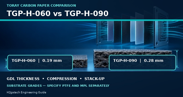
Toray TGP-H-060 and TGP-H-090 are carbon-paper substrate grades commonly evaluated for PEM fuel cell gas diffusion layers. Their clearest official difference is thickness: Toray lists representative values of 0.19 mm for TGP-H-060 and 0.28 mm for TGP-H-090. The 0.09 mm, or 90 µm, difference can change the cell stack-up, gasket relationship, compression response, contact condition, and gas-transport path.
The thicker grade is not automatically better, and the thinner grade is not automatically more efficient. A carbon-paper designation also does not tell a buyer whether PTFE treatment or a microporous layer (MPL) is included. The correct choice depends on the finished GDL construction and the actual cell hardware, operating conditions, and validation method.
The Short Answer
TGP-H-060 is the thinner starting point and may suit hardware with a tighter through-plane stack-up or an existing design qualified around approximately 190 µm carbon paper. TGP-H-090 provides about 90 µm more uncompressed substrate thickness and may be selected when the cell design needs a thicker diffusion medium, a different compression window, or greater separation between the catalyst layer and flow-field features. These are design starting points, not performance guarantees.
Select the substrate together with the hydrophobic treatment, MPL, finished thickness, dimensions, compression target, gasket, flow field, humidity strategy, and current-density range. Confirm the decision in a matched single-cell test before freezing an MEA or stack bill of materials.
Official Toray Substrate Data at a Glance
Toray property | TGP-H-060 | TGP-H-090 | Engineering interpretation |
Representative thickness | 0.19 mm (190 µm) | 0.28 mm (280 µm) | H-090 is 90 µm thicker before treatment and compression. |
Through-plane electrical resistance | 80 mΩ·cm | 80 mΩ·cm | The representative substrate value does not predict finished-cell contact resistance. |
In-plane electrical resistance | 5.8 mΩ·cm | 5.6 mΩ·cm | Very similar listed values; test the finished GDL and interfaces. |
Gas permeability | 1900 | 1700 | Toray units: ml·mm/(cm²·hr·mmAq); compare by the same method. |
Porosity | 78% | 78% | Equal listed porosity does not mean identical pore pathways or compressed behavior. |
Bulk density | 0.44 g/cm³ | 0.44 g/cm³ | The main published distinction remains thickness, not density. |
Surface roughness | 8 µm | 8 µm | Representative substrate roughness; a finished MPL changes the interface. |
Tensile strength | 5 kgf/cm | 7 kgf/cm | Handling response still depends on cut geometry and conditioning. |
Important: Toray identifies these as representative values rather than guaranteed product specifications and advises contacting the company about measurement methods. An RFQ should therefore distinguish supplier data-sheet values from the acceptance limits required for the finished H2gatech component.
Carbon Paper Grade Is Not the Same as a Finished GDL
A bare carbon-paper substrate is only one part of a practical gas diffusion layer. Fuel-cell GDLs are often hydrophobically treated, commonly with PTFE, and many include an MPL on the catalyst-facing side. The MPL is typically a fine carbon-based layer with a hydrophobic binder. It changes the surface presented to the catalyst layer and can influence water retention, water removal, gas access, electrical contact, and mechanical support.
For this reason, “TGP-H-060” or “TGP-H-090” by itself is not a complete purchasing description. Two suppliers can start with the same carbon paper and deliver different finished GDLs because their PTFE content, MPL composition, coating amount, drying, heat treatment, final thickness, and inspection methods differ.
Finished-GDL field | What the purchase specification should state |
Substrate | Toray grade, lot, dimensions, orientation, and representative raw thickness |
Hydrophobic treatment | PTFE or other treatment type, target amount or class, treatment side, and acceptance method |
Microporous layer | Present or absent, side, loading or thickness basis, surface condition, and defect criteria |
Finished thickness | Measurement method, conditioning, sampling positions, and tolerance before cell compression |
Compressed behavior | Thickness and resistance at a defined pressure or clamping condition |
Electrical properties | Through-plane resistance or area-specific resistance using a defined fixture and pressure |
Transport properties | Gas permeability and any relevant liquid-water or capillary characterization |
Geometry and packaging | Cut size, holes, edge quality, orientation marks, cleanliness, lot identity, and protective packaging |
How Thickness Changes the Cell Stack-Up
The 90 µm substrate difference affects more than the space occupied by one sheet. A five-layer MEA has a GDL on both sides; replacing both sides with a thicker grade can change the uncompressed diffusion-media contribution to the cell stack-up by approximately 180 µm before PTFE, MPL, compression, and manufacturing variation are considered. Whether that matters depends on the gasket design and the clamping method.
If the gasket and plate geometry remain unchanged, a thicker GDL may experience more compression or may increase load on the MEA. A thinner GDL may reduce contact in hardware designed around a thicker medium. Both situations can cause nonuniform current distribution, higher contact resistance, leakage risk, catalyst-layer damage, or intrusion into flow-field channels. The safe approach is to calculate the complete compressed stack, then verify it in the actual fixture.
For a broader comparison of diffusion media, see SIGRACET 28 BC vs Toray TGP-H-060.
Compression Is a System Variable, Not a Universal Percentage
Carbon paper must provide contact while preserving a connected pore network. Increasing compression may lower some electrical contact losses, but too much compression can reduce porosity, restrict gas paths, change water transport, damage the MPL, deform the substrate near channels, or create local stress at the catalyst layer. Too little compression can leave high-resistance gaps or poor sealing support.
Do not choose TGP-H-060 or TGP-H-090 from an isolated compression percentage. Define the cell hardware, gasket thickness, active area, clamping method, plate land and channel geometry, finished GDL construction, and target compressed thickness. Record the same assembly procedure for every comparison sample.
Gas Transport and Water Management
The U.S. Department of Energy describes GDLs as the layers that transport reactants toward the catalyst and remove product water. It also notes that PTFE and an MPL can help balance water retention and water release. That balance is especially important on the cathode, where liquid water is produced during hydrogen-air PEM fuel cell operation.
Toray lists representative gas permeability of 1900 for H-060 and 1700 for H-090 in its stated measurement units. This does not prove that a finished H-060 GDL will always transport gas better in a working fuel cell. MPL loading, PTFE treatment, compression, temperature, pressure, relative humidity, stoichiometry, water production, and the plate channels may have a larger effect on the actual two-phase transport behavior.
When TGP-H-060 May Be the Better Starting Point
· The existing cell, gasket, and plate stack-up were designed and qualified around approximately 0.19 mm substrate thickness.
· A thinner diffusion medium is needed to meet the compressed assembly height without increasing seal or MEA stress.
· The flow-field design and current-density target have already been validated with an H-060-based finished GDL.
· Handling, cutting, flatness, channel intrusion, and contact remain acceptable at the project’s clamp load.
· The development plan is comparing PTFE or MPL options while keeping the substrate grade constant.
When TGP-H-090 May Be the Better Starting Point
· The hardware and seal design require a thicker diffusion medium or more uncompressed stack-up height.
· The application needs a different compression response or mechanical separation from flow-field features, subject to validation.
· A qualified legacy design already uses H-090 and changing the substrate would create unnecessary revalidation risk.
· The selected finished GDL treatment and MPL have been optimized and approved on the H-090 base paper.
· Cell testing confirms acceptable transport, contact resistance, sealing, and durability at the intended operating window.
Should the Anode and Cathode Use the Same Carbon Paper?
Not necessarily. Hydrogen-side and air-side conditions are different. The cathode must manage product water while maintaining oxygen access; the anode has different reactant, humidity, and water-transport conditions. A development team may use the same finished GDL on both sides to simplify sourcing and assembly, or use different substrates and treatments to target each side.
If the two sides differ, drawings and packaging should make orientation unmistakable. Specify substrate grade, PTFE treatment, MPL side, finished thickness, cut geometry, and anode/cathode identification for each side. Do not rely on visual appearance alone during assembly.
To place the GDL decision within the complete component, review CCM vs MEA: What Fuel Cell Buyers Should Specify.
A Practical Single-Cell Validation Plan
Validation stage | What to control or record |
1 Lock the comparison | Keep the CCM, active area, gasket, bipolar plates, compression method, gas conditions, temperature, humidity, and break-in protocol unchanged. |
2 Inspect incoming GDLs | Record substrate grade, lot, treatment, MPL side, dimensions, finished thickness, mass, flatness, visible defects, and orientation. |
3 Confirm assembly | Check total stack-up, gasket relationship, tightening sequence, compressed condition, alignment, and leak performance. |
4 Establish baseline | Run the same conditioning and polarization protocol; record voltage, pressure behavior, high-frequency resistance or impedance, and repeatability. |
5 Challenge water balance | Evaluate the humidity, stoichiometry, temperature, current density, and duty points that represent the intended application. |
6 Review after testing | Inspect imprint, cracking, delamination, fiber intrusion, flooding evidence, dry regions, edge damage, and dimensional change. |
7 Approve the complete part | Freeze substrate, PTFE, MPL, dimensions, inspection, packaging, lot traceability, and change-notification requirements together. |
H2gatech Engineering Note
When H2gatech reviews a request for Toray carbon paper, the first question is whether the customer needs bare substrate, a treated gas diffusion backing, or a finished GDL with an MPL. The next questions concern the cell drawing, gasket, target compressed thickness, anode/cathode orientation, operating window, and acceptance test. This prevents a familiar purchasing error: ordering the correct substrate code but the wrong finished layer structure.
For a new design, begin with a small, traceable sample matrix rather than changing multiple variables at once. One useful comparison keeps the CCM and hardware fixed while testing H-060- and H-090-based GDLs with otherwise matched treatment and MPL. A second matrix can then adjust PTFE or MPL after the thickness effect is understood.
For the information needed in a custom order, use How to Specify a Custom Fuel Cell MEA.
Explore H2gatech’s component options at Membrane Electrode Assembly.
RFQ Checklist for H-060- or H-090-Based GDLs
RFQ section | Information to provide or agree |
Application | Fuel-cell type, active area, anode/cathode side, stack power or laboratory purpose, and expected duty cycle |
Substrate | TGP-H-060 or TGP-H-090, acceptable alternative policy, source traceability, dimensions, holes, and orientation |
Treatment | Bare or hydrophobic treatment; material, target amount or class, side, and acceptance method |
MPL | Required or not; side, loading or thickness basis, formulation constraints, surface quality, and edge coverage |
Thickness | Finished uncompressed thickness, measurement method, tolerance, and compressed thickness at a defined load |
Cell hardware | Flow-field pattern, land/channel dimensions, gasket material and thickness, plate material, and clamping method |
Operating window | Temperature, pressure, differential pressure, humidity, stoichiometry, current-density range, contaminants, and cycling |
Acceptance | Dimensions, appearance, mass, thickness, resistance, permeability, defects, sample plan, lot traceability, and packaging |
Common Selection Mistakes
· Treating H-060 and H-090 as finished GDL specifications instead of substrate designations.
· Assuming the thicker paper will automatically improve durability or water management.
· Changing substrate thickness without recalculating gasket and compressed cell stack-up.
· Comparing two GDLs that also have different PTFE and MPL constructions, then assigning the full result to carbon-paper thickness.
· Using the data-sheet gas-permeability number as a direct prediction of two-phase fuel-cell performance.
· Failing to mark MPL orientation and anode/cathode identity in the drawing and packaging.
· Freezing a material from one polarization curve without repeat samples, water-balance testing, and post-test inspection.
Frequently Asked Questions
What is the thickness difference between TGP-H-060 and TGP-H-090?
Toray lists representative substrate thicknesses of 0.19 mm and 0.28 mm, respectively. The difference is 0.09 mm, or 90 µm, before hydrophobic treatment, MPL application, manufacturing variation, and cell compression.
Is TGP-H-090 better because it is thicker?
No. Thickness changes stack-up and transport distance, but suitability depends on the finished GDL, compression, gasket, flow field, humidity, current density, and validation results.
Does TGP-H-060 include an MPL?
The substrate designation alone does not establish an MPL. State separately whether the required part is bare paper, PTFE-treated backing, or a finished GDL with an MPL.
Can H-060 and H-090 use the same gasket?
Only if the complete compressed stack-up and sealing design support it. A 90 µm substrate difference per side can materially change the assembly, especially when both anode and cathode GDLs are changed.
Which grade has higher gas permeability?
Toray lists representative values of 1900 for H-060 and 1700 for H-090 in its stated units. These substrate values should not be used alone to predict finished-cell performance.
Can the anode use H-060 while the cathode uses H-090?
Yes, a mixed design is possible if each side is specified, oriented, packaged, and validated correctly. The benefit must be demonstrated in the intended cell.
Discuss a Custom GDL or MEA With H2gatech
Send H2gatech your cell drawing, active area, substrate preference, PTFE and MPL requirements, anode/cathode orientation, gasket stack-up, compression method, operating window, test protocol, quantity, and documentation needs. The engineering team can help define a traceable sample configuration for evaluation. Contact H2gatech to discuss the project.
Technical References
• Toray Industries — TORAYCA™ Carbon Paper Data Sheet — official representative data for TGP-H-060, TGP-H-090, and other TGP-H-series carbon-paper substrates.
• U.S. Department of Energy — Parts of a Fuel Cell — official overview of GDL, PTFE, MPL, reactant transport, water removal, gaskets, and bipolar plates.
• U.S. Department of Energy — High Performance Gas Diffusion Layer — primary DOE-funded development work illustrating trade-offs among hydrophobic treatment, porosity, conductivity, and water management.