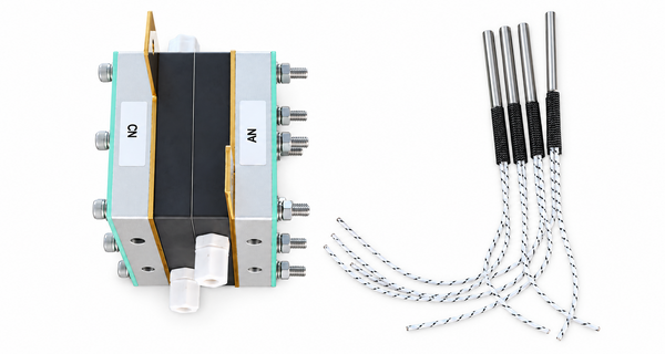

5 x 5 PEM Fuel Cell Single Cell Test Fixture
5 x 5 PEM Fuel Cell Single Cell Test Fixture With Heating Rods
A PEM fuel cell single cell test fixture holds one membrane electrode assembly between defined flow-field, current-collection, sealing, and compression interfaces. Connected to a suitable fuel cell test station, it allows researchers and engineers to evaluate an MEA under controlled gas, temperature, pressure, humidity, and electrical-load conditions. The fixture is test hardware; the quality of the result still depends on the complete setup and protocol.
H2gatech’s 5 x 5 cm fixture provides a 25 cm² effective area, line sealing, 6 mm gas-tube connections, and four removable heating rods. Its format is suitable for laboratory MEA development, material comparison, polarization testing, diagnostic work, and incoming or sample validation when the same hardware and operating procedure are used consistently.
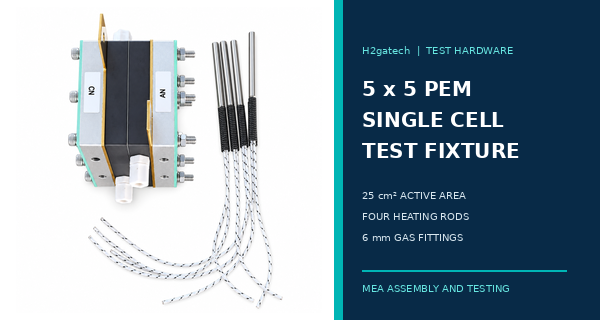
The fixture provides the mechanical and fluidic cell hardware; gas control, temperature control, electrical loading, safety equipment, and the test protocol must be defined separately.
What the Fixture Is Designed to Do
The fixture creates a repeatable way to assemble a single PEM fuel cell around a 5 x 5 cm active area. Two carbon plates provide the internal cell hardware, two gold-plated plates support current collection, and two end plates apply the mechanical clamping structure. Quick-connect fittings route reactant gases, while four heating rods provide an external means of heating the assembly when connected to an appropriate controller and temperature-sensing arrangement.
With compatible instruments, the assembled cell can be used for polarization curves, voltage and power measurements, electrochemical diagnostics, hydrogen crossover evaluation, and analysis of activation, ohmic, and mass-transport behavior. The fixture itself does not generate these measurements and does not replace the electronic load, potentiostat, gas supply, humidification equipment, flow and pressure controls, sensors, data acquisition, ventilation, or hydrogen-safety system.
For the component placed inside the fixture, see H2gatech Membrane Electrode Assemblies.
Product Specifications at a Glance
Specification | Supplied value | Engineering note |
Effective area | 5 x 5 cm or 25 cm² | Use 25 cm² when converting current to current density. |
Main structure | Two carbon plates, two gold-plated plates, and two end plates | Confirm the flow-field pattern and plate details for a project when required. |
Gas connections | Four push-in fittings for 6 mm tubing | Check anode and cathode inlet and outlet orientation before connection. |
Tube size | 6 x 4 mm PU tube | Verify gas compatibility and project pressure requirements. |
Sealing method | Line sealing | Gasket thickness and assembly compression must match the MEA stack-up. |
Heating method | Four removable heating rods | Use controlled heating and suitable temperature sensing. |
Heating-rod rating | 220 V / 40 W | Confirm the final product label, wiring, controller, and electrical protection. |
Fixture dimensions | Approx. 150 x 105 x 130 mm | Final dimensions and appearance are subject to the delivered product. |
Fixture weight | Approx. 2324 g | Plan stable bench placement and strain relief for tubing and cables. |
Why Heating Rods Matter in Single Cell Testing
PEM fuel cell behavior changes with cell temperature because reaction kinetics, membrane resistance, water transport, gas humidity, and heat rejection are temperature dependent. Heating the fixture helps bring the cell toward a defined operating condition before data are recorded. It also supports comparison between MEAs when the temperature setpoint, sensor position, stabilization rule, and surrounding gas conditions are kept consistent.
Four heating rods do not by themselves prove that the complete active area is at one uniform temperature. Actual temperature distribution depends on rod fit, controller behavior, sensor placement, plate conductivity, insulation, gas flow, humidification, ambient conditions, and heat generated by the cell. Record both the controller setpoint and the measured fixture or cell temperature, and allow a defined stabilization period before each test step.
Why Test Hardware Can Change the Result
The same MEA can produce different results in different fixtures. Flow-field geometry affects reactant distribution and water removal. Gasket thickness and bolt loading affect compression. Contact surfaces influence electrical resistance. Plate temperature and gas conditions affect membrane hydration. For this reason, a polarization curve should always be reported together with the relevant hardware and operating conditions.
The European Commission Joint Research Centre notes that both testing hardware and the protocol influence measured PEM fuel cell performance. Its reference-hardware work emphasizes uniform and documented flow, pressure, temperature, and reactant concentration when results are compared between laboratories. A compact fixture is therefore most useful when the assembly and test method are treated as controlled parts of the experiment, not as unrecorded accessories.
For planning the MEA geometry and validation requirements, read How to Specify a Custom Fuel Cell MEA.
Convert Fixture Current to Current Density Correctly
Current density is the measured cell current divided by the geometric active area. For this 25 cm² fixture, the calculation is current density in A/cm² = current in A ÷ 25 cm². Report both current and current density, and confirm that the catalyst-coated area, GDL overlap, gasket window, and flow-field area use the same active-area definition.
Total cell current | Current density for 25 cm² |
1 A | 0.04 A/cm² |
5 A | 0.20 A/cm² |
12.5 A | 0.50 A/cm² |
25 A | 1.00 A/cm² |
37.5 A | 1.50 A/cm² |
50 A | 2.00 A/cm² |
Prepare the MEA and Seal Stack Before Assembly
A good test starts with a fully defined layer stack. Record the membrane or CCM grade, catalyst and loading on each side, GDL and MPL grade and orientation, frame or sub-gasket material, active area, external dimensions, and gasket thickness. Check that the anode and cathode sides are identified and that the gas openings, active area, GDL, seal, and flow field align without blocking the intended flow path.
Compression must be controlled because too little compression can increase contact resistance or leakage, while excessive compression can damage the GDL, change pore structure, intrude material into channels, or overstress the membrane and seal. Use a documented tightening sequence and an approved torque, gap, or compressed-thickness method that is appropriate for the supplied hardware and MEA stack-up.
For layer definitions, review CCM vs MEA and What Buyers Should Specify.
What Should Be Controlled for Comparable Polarization Curves
Control area | Information to keep constant and report |
Cell hardware | Same fixture, flow field, contact surfaces, fittings, assembly orientation, and active-area definition |
Mechanical setup | Same GDLs, gaskets, tightening sequence, torque or gap, and compression history |
Reactants | Hydrogen and air or oxygen grade, contaminant limits, inlet flow or stoichiometry, and purge settings |
Water management | Humidifier temperatures, inlet relative humidity, condensate control, and cathode drainage behavior |
Pressure | Anode and cathode inlet and outlet pressure, backpressure, and differential-pressure limit |
Temperature | Controller setpoint, sensor location, measured cell temperature, stabilization time, and ambient condition |
MEA state | Break-in method, prior operation, storage history, test order, and rest periods |
Data method | Load-step sequence, dwell time, sampling rate, stability criterion, HFR or EIS method, and correction rules |
H2gatech Engineering Note
When this fixture is used to compare two MEAs, change one primary variable at a time. Keep the fixture, flow field, GDL, gasket, compression, break-in, gas conditions, temperature, and measurement sequence unchanged wherever the experiment allows. If several materials or assembly conditions change together, the polarization curve cannot identify which change caused the result.
Before ordering, send H2gatech the MEA external dimensions, active area, layer structure, GDL thickness, gasket or frame thickness, planned operating temperature, pressure range, gases, test-station tubing, heater-controller interface, and required accessories. This review helps avoid a fixture that accepts the active area but does not match the customer’s complete sealing, compression, connection, or control arrangement.
For related outgoing checks, see Fuel Cell MEA Quality Inspection Before Shipment.
Safety and Equipment Scope
Hydrogen testing combines flammable gas, electrical current, hot surfaces, pressure, and mains-powered heaters. Operate the fixture only in a suitably designed test area with trained personnel, ventilation, gas detection where required, pressure relief, leak-check procedures, electrical grounding and protection, emergency shutdown, and written startup and shutdown sequences. Never energize a loose heating rod, touch hot hardware, or assume a fitting is gas-tight without verification.
The supplied fixture description identifies the mechanical cell hardware, fittings, locking components, and heating rods. It does not state that a heater controller, thermocouple, humidifier, mass-flow controller, backpressure regulator, electronic load, potentiostat, gas detector, or complete safety enclosure is included. Define the full test-system scope in the quotation so that hardware and responsibility are clear.
Buyer Checklist for a Single Cell Test Fixture
RFQ section | Information to provide or confirm |
MEA geometry | Active area, outer size, catalyst area, GDL outline, frame or gasket, holes, side identification, and tolerances |
Flow-field requirement | Pattern, channel dimensions if controlled, gas direction, inlet and outlet locations, and drainage needs |
Compression plan | GDL thickness, seal thickness, target compression, tightening method, and mechanical limit |
Gas connections | Tube outside and inside diameter, fitting type, material compatibility, flow range, pressure, and orientation |
Heating requirement | Voltage, power, rod quantity, controller, sensor type and position, target range, and electrical protection |
Electrical interface | Current range, current-collector connection, cable or busbar interface, contact protection, and instrumentation |
Test objectives | Polarization, HFR, EIS, CV, crossover, durability, conditioning, teaching, or material screening |
Documentation | Drawing, parts list, operating instructions, inspection record, spare seals, spare heaters, and packing list |
Common Mistakes to Avoid
· Treating the fixture as a complete test station and overlooking flow, pressure, humidity, load, control, sensing, and safety equipment.
· Using 25 cm² in the quotation but a different catalyst-coated area or gasket window in the assembled cell.
· Changing gasket thickness, GDL grade, or tightening method between samples and attributing every voltage change to the MEA.
· Reporting only the heater setpoint without recording the measured fixture temperature and stabilization rule.
· Connecting heating rods directly without a compatible controller, sensor, grounding, protection, and verified wiring arrangement.
· Comparing curves from different break-in histories, gas humidity, pressure, flow, dwell time, or data-processing rules.
· Opening the fixture while it is hot, pressurized, energized, or insufficiently purged.
Frequently Asked Questions
What is the active area of this fixture
The effective area is 5 x 5 cm, equal to 25 cm². At 25 A total current, the corresponding current density is 1.0 A/cm².
Why are four heating rods used
They provide distributed heat input to the fixture. Actual temperature uniformity still depends on installation, control, sensing, plate conduction, insulation, gas conditions, and cell heat generation.
Can the fixture measure an MEA by itself
No. It holds and heats the single cell. Measurement requires a compatible gas-delivery system, electronic load or potentiostat, sensors, controls, data acquisition, and safety equipment.
Can it test both three-layer and five-layer MEAs
Potentially, if the complete layer stack, GDLs, seals, external geometry, compressed thickness, and flow-field interfaces are compatible. Confirm the intended stack-up before ordering.
Does the same torque work for every MEA
No universal value should be assumed. The correct assembly endpoint depends on hardware design, fasteners, GDL and gasket properties, sealing target, and the allowed compression of the complete stack.
Are results directly comparable with another laboratory
Only when the relevant hardware, MEA state, assembly, gases, pressure, humidity, temperature, conditioning, load sequence, and data rules are aligned or fully reported.
Discuss a Custom Single Cell Test Fixture With H2gatech
Send H2gatech your MEA drawing, active area, layer structure, GDL and gasket thickness, planned gas conditions, pressure range, temperature-control method, electrical-load range, connection requirements, accessories, and test objectives. The engineering team can review whether the standard 5 x 5 cm configuration is suitable or whether the fixture interfaces should be customized. Contact H2gatech to discuss the test setup.
Technical References
• European Commission JRC - EU Harmonised Test Protocols for PEMFC MEA Testing in Single Cell Configuration - industry-supported reference conditions and methods for comparable PEMFC MEA performance and durability testing.
• European Commission JRC - Development of Reference Hardware for Harmonised Testing of PEM Single Cells - explains how single-cell hardware and operating conditions influence inter-laboratory MEA results.
• U.S. Department of Energy - Procedure for Performing PEM Single Cell Testing - technical procedure covering controlled single-cell testing, conditioning, polarization, and diagnostic measurements.